
How to fit an attachment to your excavator: hitch, pins and lock
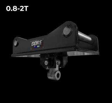
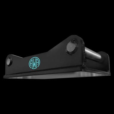
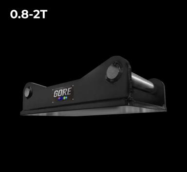
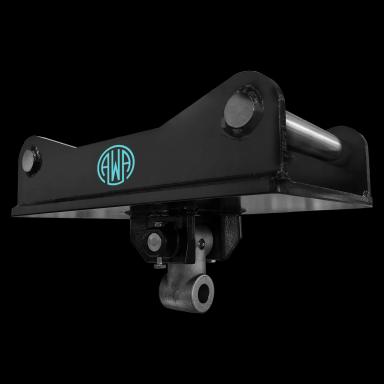
A hitch (in Swedish grindfäste, "S40 fäste") sits on the attachment and locks into the quick coupler on your machine. This guide shows how to identify what you have, how an auger drive is fitted with its mounting frame and how a breaker is pinned on. Torques are the ones printed in our manuals. Where a manual is silent, we say so.
Updated 2026-10-18
Short answer
Read the marking on the coupler your machine has, match it with the S size of the attachment hitch (S30, S40, S45, S50, S60 or S70) and confirm both on the product page. Fit with two people, on flat ground, engine off. On an AWA or GORE auger drive frame, the threaded mounting pin is torqued to 100 Nm and through-bolt nuts to 26 Nm. Then check that the drive swings freely.
Two parts, two jobs
The hitch (grindfäste, S40 fäste) is on the attachment. The quick coupler (snabbfäste) is on the machine. We sell the attachment side. The coupler is opened, locked and checked the way its maker describes. We publish no lock procedure for it because it is not our component.
An S number names the attachment hitch standard. It is not the same label as S4 or S5, which name the shaft series of an auger drive (see how to fit an auger bit). MS01, MS03 and MS08 are Lehnhoff sizes, a different standard from the S sizes. Do not treat S and MS as interchangeable.
Step 1: identify what you have
- Read the maker, model and size on the coupler fitted to your machine. Take a photo of the marking.
- Read the size on the hitch of the attachment: S30, S40, S45, S50 or S60 and S70, or MS01, MS03 or MS08 for a Lehnhoff hitch.
- Compare both with the product page and with the matching hitch page: S30, S40, S45, S50, S60, S70.
- The same S number can come in more than one variant, so machine model and weight class alone do not confirm a fit. If the marking is unclear, send us photos of the marking and the attachment with the article number.
Step 2: pick up the attachment and lock it
Picking up and locking follow your coupler maker's instructions and your machine's manual. Do not lift or work with the attachment until the coupler's own locking check is done.
Fitting an AWA or GORE auger drive: the mounting frame
The drive is fitted to the machine through a mounting frame. The auger drive manual has one page per frame type. The manual is e-mailed from the "Download manual" button on the product page. Page numbers refer to it.
| Mounting frame | Manual page |
|---|---|
| Single pin hitch | 11 |
| Double pin hitch | 12 |
| Cradle hitch | 13 |
| Truck crane (mounting block) | 14 |
| Skid steer loader | 15 |
From the manual, pages 10 to 15:
- Work in pairs. Two skilled operators whenever drive parts are fitted or removed. Check the weight on the data plate and use suitably rated lifting equipment.
- Park the machine on flat ground with the hand brake on, the hydraulic circuit locked out and the engine off.
- Check that the mounting frame is the right model and type for your machine. Clean the frame and the attachment points.
- Lubricate all components on assembly.
- Lay the drive horizontal with the output shaft towards the machine.
- Fit the drive to the frame. A threaded mounting pin has a locating plate that sits on a peg in the hood ear: align the holes, fit pin, washer and nylon insert nut and torque to 100 Nm. A through-bolted mounting pin is pushed fully home with the through-bolt holes lined up; fit the through bolts and nylon insert nuts and tighten to 26 Nm.
- Fit the frame to the machine. Single pin hitch: through-bolted pins in all cases, nuts to 26 Nm, spacers if needed to centre the frame. Double pin and cradle hitch: a linch pin (push the pin home and fit the linch pin) or a through-bolted pin (26 Nm).
- Truck crane: the mounting block goes between the hook attachment ears; torque the threaded pin to 100 Nm, then insert the mounting pin and spring clip. Skid steer loader: slot the top of the skid steer frame under the top edge of the mounting frame, swing it to vertical and push the locking levers down fully.
- Check that the drive swings freely in all directions.
Fitting a hydraulic breaker on the arm
This is the pin-on procedure from the breaker manual, section 4-3. A breaker on a hitch is picked up by the coupler as in step 2. Hoses are covered in how to connect hydraulic hoses.
- Set the breaker on horizontal ground without mud or dust.
- Take the two pins out and remove the bucket. With the bucket cylinder retracted the installation is easier.
- Move the machine close, align the arm pin hole with the pin hole of the breaker and insert the pin.
- Lift the boom and set the breaker on wood blocks. Extend the bucket cylinder, fit it to the bucket link hole and insert the pin.
- Fit the stop rings, align the bolt holes, insert the bolts and lock them with a double nut. A single nut can shorten the life of the bolt or let it work loose.
- Never put a hand or finger in a pin hole, and keep everyone away from the arm and bucket while you align.
Weld-on brackets
We list weld-on brackets (S30/150, S30/180, S40, S45, S50, S60 and S70) as separate articles from the double-pin attachment brackets. A weld-on bracket is fitted by welding, according to the documentation for the construction it goes on. That is structural work: use a qualified welder and the attachment maker's drawing. We do not publish weld dimensions or procedures here. Contact us with the article number to find out what documentation exists.
Current range
Hitches in the range
The cards show current price and stock. Check the hitch size against your machine before you order.
Frequently asked
Does S40 mean the attachment fits my machine?
Is a grindfäste the same as a quick coupler?
Is S4 on an auger the same as S40?
How tight must the mounting pins be?
See the range for yourself
Browse the current range and check each product’s specifications, price and availability.